
One of the most prevalent conveyor systems within a wide varied of manufacturing applications is the “Power and Free” conveyor. It is commonly used within automotive manufacturing facilities; examples include moving subassembly, or conveying engines to the mainline.
What is a Power and Free Conveyor?
A Power and Free conveyor allows for non-synchronous movement, which permits loads held by carriers to move at different paces. The conveyor is typically made up of two internal tracks; one referred to as the power track and the other the trolley track. The upper power track contains the chain and catching-dogs; and the lower track holds the trolleys which can engage and disengage (free) from the fixed spaced drive dogs within the power track. Furthermore, the trolleys are set up to mechanically auto-disengage from the power track when they reach a stopped carrier or stop station.
Power and Free systems not only move parts from point A to Point B; but they usually provide for a robust “Work in Progress” buffer. They are often mounted overhead allowing for maximizing assembly floor space, and allowing for large decouplers between assembly lines.
How to model Power and Free Conveyors in SIMUL8 2016
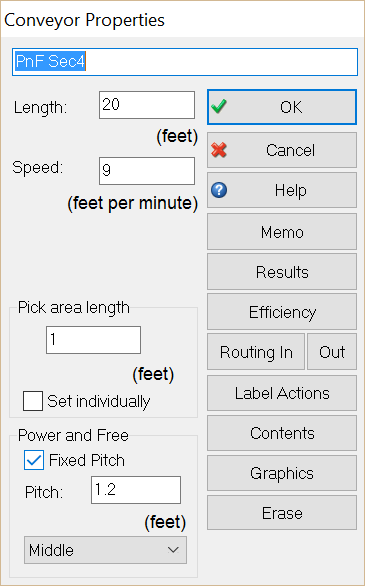
SIMUL8 2016 now contains some added features within the conveyor object that capture the significant behavior of power and free. We can now add a “Fixed Pitch” to the conveyor; which represents drive dog spacing on the power chain. Therefore, “Work items types” will only load onto a conveyor section according to the fixed pitch value. Yet, once carriers are traveling upon conveyors, they may accumulate when reaching a stopped station or carrier. Lastly, starting an accumulated carrier occurs upon the fixed pitch value.
Additional details can be added within the “Attachment Point” dropdown. This allows for fine tuning the attachment point of the drive dog spacing. There are 3 values to select from: Trailing, Middle, and Leading. For example, these options allow for positioning the dog drive attachment point to the leading edge, middle, or the trailing edge of the carrier.
An Automotive Example
Let’s take a look at an automotive simulation model of delivering an engine to the mainline. In the example simulation – available for download below – we can see a Power and Free conveyance loop which delivers engines to the engine mount station within the mainline.
The simulation consists of two parallel lines – one represents the mainline carrying the vehicles, and the other represents an overhead Power and Free system. The new conveyor feature allows for the carriers to travel according to a fixed pitch, yet accumulate upon a stoppage.
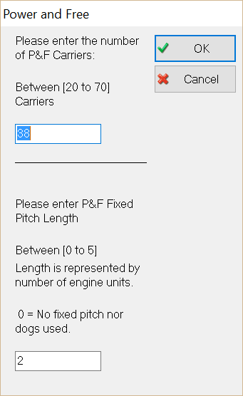
We can easily conduct a series of “what ifs” on testing the optimal number of carriers within the system, by using the input button which sets the total number of carriers. The user dialog box allows you to enter anywhere from between 20 to 70 carriers within the loop. Let’s say that we have determined that 38 carriers are optimal.
Additionally, we can conduct a similar analysis on the dog spacing within the loops respective conveyance sections. The below chart summarizes testing various drive dog spacing schemes. Here we enter the dog spacing length in the form of number of carriers that could reside within the suggested gap (i.e. 0 to 5 carriers). You can also choose to use explicit part lengths and physical lengths within your power in free model; but here we are using counts to represent physical length.
Lastly, we can also fine tune the desired dog attachment point to one of the following: Trailing, Middle, and Leading. In the above case we are using the middle of the carrier as the attachment point.
| Power and Free Fixed Pitch (units) | Net Jobs Per Hour |
|---|---|
| 0.5 | 44.4 |
| 1 | 44.4 |
| 2 | 44.38 |
| 3 | 44.22 |
| 4 | 43.37 |
| 5 | 40.38 |
The above chart suggests that a fixed pitch size of 2 carrier lengths is sufficient drive dog spacing for the proposed Power and Free system. Anything greater than 2 carrier lengths will cause a degradation in overall system throughput (net Jobs Per Hour).
Now that we can simulate Power and Free conveyors it’s easier to model the recirculation of parts, balance the lines and provide maximum material flow. Being able to simulate the carrier spacing for independent units and the speed at which these units are transported are key parameters that we as users need to have to develop our simulation models. This new feature helps users simulate complex conveyors effectively and efficiently, while at the same time helping us to create simulations that look great too!
Want to try it out?
Don’t have SIMUL8? Get in touch to request a trial.