Written by Brian Harrington on Wednesday March 9th 2016 in Technical Corner
Making the most of Simulation Control Logic
Some simulation models have some degree of complex conditional statements within their routing logic. SIMUL8 includes a programmable language that allows the user to develop logical statements and use various commands. This includes the use of variables, attributes, “IF Statements”, “Conditional Loops”, and multiple commands. These logical constructs make models powerful enough to take on very complex problems. These problems usually have a mixture of conflicting, conditional and random events. The code that is developed within a simulation model can lead the way to calibrating Programmable Logic Controllers (PLCs), creating algorithms and developing the required shop-floor ladder logic.
Whether working as an individual or as part of a larger simulation team, it is important for the success of the project to have stakeholder engagement throughout the duration of the simulation study. There should be engineers directly on, or actively working with, the team that are proficient with the proposed design or layout. As the simulation team gathers the required information to develop the model, more than likely there will be several process flow charts. Some of these process flow charts might contain the initial data to develop the complex conditional logic within the simulation.
Developing your code
Simulation models can contain a lot of realistic details such as objects that represent photoelectric sensors (also known as photo eyes) that send signals to various assets within the process. For example, a photo eye might send a signal to a conveyance system to slow down upon a certain part count, or speed up when parts counts are low. Obviously, this type of information is critical to the overall throughput and potential design of the facility. Typically, several IF-THEN statements are used throughout key objects within the model. This virtual code is usually positioned in the model where the actual sensor is located in the layout. This is exactly how the code developed within the modeling effort can be transported or translated into the actual ladder logic used on the shop floor.
Often the modeler will review the simulation code with the simulation team, particularly with the engineers responsible for programming the Programmable Logic Controllers (PLCs). This may require going through the code and conditional statements line by line. This is also an excellent time to verify and validate the code as it nears the implementation phase. Ultimately, we are transferring the knowledge developed within the model to the responsible PLC engineers.
Validating your code
Going through the code line by line is one technique, and often is sufficient to transfer the logical concept. Although, there are additional schemes that often work better, especially when the conditional statements are deeply nested and filled with complex decision points. One such scheme is to leverage the process flow charts that were supplied by the design team in the input phase. We explicitly use the supplied or derived process flow charts within the model. Any of the process charts can be easily be captured with simulation objects to form a data structure for the code to reside upon. We are actually transforming the logical process flow chart into a sub model that can receive signals, and therefore invoke code. Now we are talking much closer to the language of programming PLCs and ladder logic. Let’s take a look at a simplified example.
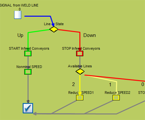
The simplified simulation will focus on a portion of a manufacturing facility with a single input line which is feeding three parallel welding lines. The code at hand will be shutting off feeding conveyors upon a weld machine breakdown. It will also manipulate conveyance speeds according to the number of weld machines working. In other words, when a welding machine goes down it will send a signal to stop certain conveyors, and adjust conveyor line speeds. On the contrary, upon a break restart it will start respective conveyors and adjust line speeds accordingly. The process flow chart of the breakdown logic for the weld machines has been captured in the below sub window. As mentioned above it now provides a data structure of objects to attach code and routing logic. All of the objects contained within the process flow can have internal cycle times of zero, or they can contain small representative delays. In effect we have animated the process flow chart. This in itself makes it much easier to establish simulation validation, and transfer the logic to PLC programmers.
In the example simulation both Line 1 & Line 2 have broken down; upon each individual breakdown a signal has been sent to the modeled process flow chart. In this case the second line to breakdown would have stopped the infeed conveyors (where the Xs are located) and reduced the transfer speed of the main infeed conveyor to Speed 2.
This is a simplified example with a relatively small scope to demonstrate the technique of leveraging process flow charts. This scheme proves to be useful when it comes to capturing the detailed control specifics of assets within your simulation. It also is a great communication tool for the entire team to gain buy-in to the validity of the algorithms and control code within the model. Moreover, it’s often difficult to review internal code and densely nested control statements, while almost everyone understands explicit visual process flow diagrams.
This is where I have found that when working with simulation teams that are using control logic diagrams it is best to match them as closely as possible. This can be cleverly achieved by modeling them in a neatly contained sub window! It also is an excellent visual of how often certain events are occurring. For example, how many signals adjusted the infeed speed? All of this information can easily be derived from the results within the logic model. When the team can recognize algorithms and see that the model is incorporating them on a one-to-one basis it creates not only buy-in… but ownership.
Want to Try it Out?
Download the example simulation.